Classical event logs have the fundamental shortcoming of describing process behavior only in isolated process executions from the viewpoint of a single case entity. Most real-life processes involve multiple entities and process executions are not isolated but tightly connected – through actors and entities involved in multiple executions. This post summarizes how event graphs are a better model to describe and query such dynamics. I explain the basic ideas and how to construct a graph from an ordinary event table. By Dirk Fahland.
Classical event logs – the basis for all process mining – use a case identifier attribute to study the behavior in a trace: group all events with the same case identifier value and order them by time. We then can study the temporal ordering of process activities along the sequence of events to get insights into the process. The most basic temporal relation is the directly-follows relation: in a trace <e1,e2,e3,e4,e5,…> event e4 directly follows event e3.
But most real-life event data has more than one case identifier attribute. This forces to either leave out events or directly-follows relations or to squeeze events under a case identifier where they don’t really belong.
Sequential Event Logs over Multiple Entities
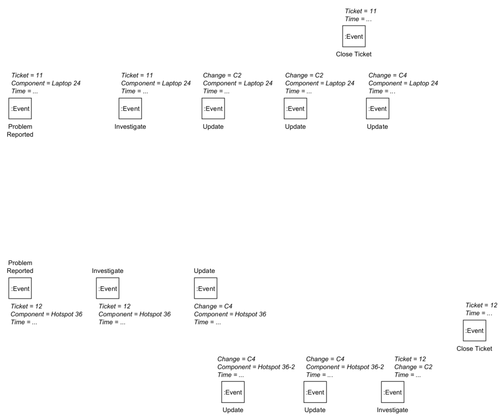
Consider the event table shown below. It has the standard event log attributes: action, time(stamp), but lacks a case identifier column that is defined for every event.

Most real-life event data is like this in their source system. The event data above most likely originates from three different tables
- Component
- Ticket with a foreign key to Component
- Change with a foreign key to Component
Creating a classical event log that contains all the events is impossible – unless one is willing to accept false information such as event duplication, or false directly-follows relations. For example, if we engineered a case identifier that separates events according to the horizontal line in the above table,
- there seems to be rework with Update twice in the second case while the Update events occur on two different Components thus only on Hotspot 36 the activity Update is repeated,
- there seems to be an Update in the first case after Close Ticket already occurred
- the Update event in Change C4 at 21-06-2020 11:10 would no longer directly follow the Update event in Change C4 at 20-06-2020 10:40.
All this together makes it hard to answer the following question: Which problems preceded (possibly caused) the final Update on Laptop 24?
In the following, we explain how a graph-based structure based on the concept of Labeled Property Graphs allows to naturally describe this data. With the graph-based model, we can avoid introducing false information and better answer questions like the cause for the final update on Laptop 24.
What is a labeled property graph?
A labeled property graph has nodes and edges (called relationships).
- Each node has one or more Labels that give the node a type. We will use the labels Event and Entity to model events and entities.
- Each edge (relationship) has a Label that semantics to the relation between nodes. We will use the labels DF (one Event node directly follows another Event node) and CORR (one Event node is correlated to a specific Entity node).
- Each node and each relationship can have multiple properties (attribute-value pairs)
By using relationships between nodes in a graph, each Event can be correlated to multiple Entity node and each Event nodes can have multiple preceding and succeeding Event nodes (via DF) allowing model multiple DF-paths (one per entity).
Here is how you can construct such an event graph using these concepts.
Step 1: Import all events
Every event record in the input event table becomes an Event node. Every attribute of the event record becomes a property. We get the following graph of just Event nodes with properties.
Step 2: identify and materialize entities
In classical event log construction, we now would pick a unique case identifier column.
In event graph construction, we now identify which attributes refer to entities – and there can be multiple in the data. We pick the ones we are interested in.
- In our example, we pick Ticket, Component, Change as entity identifier attributes.
- For each value of an entity identifier attribute, we create an Entity node of this type and id, and
- For each Event node referring to this entity, we create a CORR edge (relationship) from the Event node to the corresponding Entity node.
This results in the following graph.

Note how most events are correlated to more than one entity.
Step 3: construct directly-follow edges per entity
In classical event logs, all events related to the same case identifier are ordered by time into a trace.
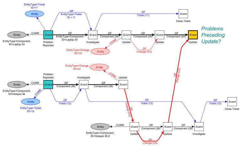
In an event graph, all events correlated to the same Entity node (via CORR edges) are ordered by time and we create a directly-follows DF edge between any two subsequent events. We store in the DF edge properties for which entity each DF edge holds. Doing this for the Entity node for Ticket = 11 results in the following graph.

We obtain a DF-path over three events from Problem Report via Investigate to Close Ticket. This DF-path states: “Entity Ticket=11 observed the sequence <Problem Report, Investigate, Close Ticket>”.
We have to do this for each Entity node for which we want to study behavior. The image below shows all resulting DF-paths over all events for all entities, but for readability we show only the CORR edge to the first event of a path.

Done. This graph fully describes the behavioral information contained in the original event table using local DF-relations per entity.
What does the event graph show?
Looking at the DF-paths, we can directly see
- We have 2 similar Ticket paths <Problem Report, Investigate, Close Ticket> and <Problem Report, Investigate, Investigate, Close Ticket>
- We have 2 Change paths only involving Update events but differing in the number of Update events.
- we have 3 separate Component paths following 3 completely different variants <Problem Reported, Investigate, Update, Update, Update>, <Problem Reported, Investigate, Update>, and <Update, Update, Investigate>
The striking difference in complexity of paths for the three different component types can be explained by the very different nature of the entities.
- A Ticket is what is closest to a classical case entity describing a process execution for a relatively structured process, i.e., it captures the problem analysis process triggered by a user until the problem is solved.
- A Component is not a typical case entity because it is a persistent object that exists beyond process executions. It typically comes back in many different process executions. Just our example is a bit too short to show another problem, say with Laptop 24. Also actors/resources fall into this category. As a result, their DF-paths will most likely follow more unique variants – requiring other kinds of analysis than typical process discovery.
- A Change is a bit similar to a process execution entity, but a change behaves differently than a Ticket. It is more unstructured (various kinds of Update events further specified by the Note attribute).
We do see the different natures back in the way the different DF-paths synchronize in the graph.
- A component is “visited” by Tickets and Changes at various points/moments, e.g., Hotspot 36-2 is first visited by Change and then by a Ticket, while Laptop 24 and Hotspot 36 are first visited by a Ticket followed by a Change.
- A Ticket path (starting with Problem Reported) leads to a Change path starting two events later on the same Component.
- Tickets can work on a single Component (11 -> Laptop 24) or on multiple Components (12 -> Hotspot 36, Hotspot 36-2).
- While the first Change path (C2) only touches a single Component, the second Change path (C4) touches three different Components. Rework happens when a Change path touches the same Component multiple times (in this example even on 2 directly-following events).
There is more behavioral information that can be inferred in this graph, for example the dependency of Close Ticket for Ticket=12 on the final Update event of Laptop 24. Doing so requires to infer relationships between two Entity nodes and to materialize a relationship as a new derived Entity node, say between Ticket 12 and Laptop 24. We then can analyze the behavioral dependencies between two entities. How to do this is explained in this paper: https://doi.org/10.1007/s13740-021-00122-1
Can we query the graph?
Event graphs based on labeled property graphs can be stored in a graph database system such as neo4j, which allows to query the graph using a graph query language.
For example, if we want to answer our earlier question “Which problems preceded (possibly caused) the final Update on Laptop 24?” we can write the following Cypher query
MATCH
(e1:Event {Action:”Problem Reported”})-[:DF*]->(e2:Event {Action:”Update”}),
(e1) -[:CORR]-> (t1:Entity {type:”Ticket”}),
(e1) -[:CORR]-> (c1:Entity {type:”Component”}),
(e2) -[:CORR]-> (c2:Entity {type:”Component”})

WHERE

NOT EXISTS (e2) -[:DF]-> (:Event)

RETURN e1,e2,t1,c1,c2
This query matches a DF-path from a Problem Reported event e1 to an Update event e2 where e2 may not have any subsequent event (there is no outgoing DF relationship). It returns e1,e2 and the ticket t1 and component c1 correlated to e1 and the component c2 related to e2.
Applied on our example graph, it will return two matches as highlighted below: e1 matches once with Problem Reported for Ticket 11 and once with Problem Reported for Ticket 12.

Note that the first matching path only uses DF-edges of one entity (Laptop 24) while the second matching path uses DF-edges of two different Entities (Change C4 and Component 36).
The above query is very limited: it works only for one specific Update event, it does not return the actual paths, and it does not collect the different results. All of these limitations can be overcome by extending the Cypher query.
How can I get started? What else can I do?
The following open access paper https://doi.org/10.1007/s13740-021-00122-1
- Defines the full model of event graphs. It gives precise semantics to the labels Event, Entity, DF, CORR (and several others).
- Provides Cypher query templates to construct event graphs from ordinary event tables.
- to query event graphs for behavioral properties and
- to construct directly-follows models over multiple entities in a graph database.
A complete implementation for importing 5 public event logs into event graphs is available here: https://doi.org/10.5281/zenodo.3865221
Here are 5 fully prepared event graphs from 5 different public event logs, both as Neo4j database dump and as GraphML file to import and analyze.
- BPIC14 https://doi.org/10.4121/14169494
- BPIC15 https://doi.org/10.4121/14169569
- BPIC16 https://doi.org/10.4121/14164220
- BPIC17 https://doi.org/10.4121/14169584
- BPIC19 https://doi.org/10.4121/14169614
This paper uses event graphs to identify task patterns in processes by analyzing how DF-paths along cases and DF-paths along resources synchronize. https://doi.org/10.1007/978-3-030-85440-9_13
This paper uses event graphs to model and analyze patient care pathways with multi-morbid patients. https://arxiv.org/abs/2110.00291

4 thoughts on “How do Event Graphs help analyzing Event Data over Multiple Entities?”